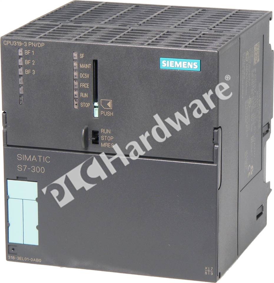
- #Siemens simatic s7 300 sf on and bf1 light blinking software
- #Siemens simatic s7 300 sf on and bf1 light blinking windows
For example, if a functional module with a diagnosis of a hardware failure, the use of symbols to determine which module has a fault where it is.


Take advantage of this feature, you can quickly obtain the status of PLC. To quickly conduct of PLC hardware failure of the diagnostic work. In the SIMATIC Manager, we can facilitate the conduct of PLC fault diagnosis. Click "OK" button to confirm Memory Reset Treatment failure in hardware, we often use the reset function.ġ. STEP 7 basic package also includes dealing with closed-loop PID control block, select the "PID Control Parameter Assignment" block allocation for closed-loop control parameters.Ĭonversion S5 file: Using the S5/S7 converters can STEP5 program into the corresponding STEP 7 program.Ĭonfiguration SIMATIC: The tool provides a multi-user function of the system configuration. The tool used to configure the MPI network, the local contact address, transmission rate and the highest contact address. Using the SIMATIC Manager, you must first set the PG-PC interface. LAD, STL, FBD preparation tools STEP 7 user program, the "ladder diagram (LAD)", "Statement List (STL)" and "functional block diagram (FBD)" programming language.
#Siemens simatic s7 300 sf on and bf1 light blinking windows
SIMATIC Manager using: SIMATIC Manager STEP 7 project, which is the main program, and also appears in the WINDOWS desktop. In addition, if there are multiple devices in the program, its commands the same, but the parameters are different, with different parameters will be only to repeat the preparation of this part of the program. However, since all instructions are in a block, each scan cycle, all programs must be executed once, even if the program did not use some parts.
#Siemens simatic s7 300 sf on and bf1 light blinking software
Since only one program file, the software management capabilities was relatively simple. Its advantages and disadvantages of that? All of the instructions are in a block, this method is suitable for single-programming projects. Block is a consecutive, in each CPU scan cycle have dealt with linear programming. All the instructions are in a block (usually the tissue block). As the name suggests, describes a linear programming implementation of a repetition of a set of instructions. Linear programming is similar to hard-wired relay logic. If any of the messages in the diagnostic buffer seem to relate to your SF/BF, but you find it difficult to understand, copy and paste them here, we might be able to help you understand the source of the problem.Briefly, the basic linear programming, linear programming with a simple non-branching structure: a simple block that contains all the commands the system.

The SF could be related to addressing issues in the program, if you are using addresses that are associated with a slave that is in BF the CPU will complain through a SF LED. It could also mean that the slave is not reachable over the Profibus network in that case check the cable, connectors and termination. Review the configuration of the slave in HWConfig. Look for messages related to slave addresses, OB86 (node failure OB), OB 121 (Programming error).Ī BF signals a Bus Fault, which means either that the bus address of the ET 200M does not match what you have configured in the HWConfig editor, or that you have not selected the correct part number for the IM 153-x head module of the ET 200M, or that the modules configured in the ET 200M do niot match the actual ones.

So your first step is to open the diagnostic buffer (CTRL + D in the Simatic Manager, or Menu- Tools- Module Information). The documents proposed are very good, but for now start with the diagnostics provided by your CPU.Įvery time an "event" happens in your program (and SF/BF are considered an event) it will be logged in the diagnostic buffer of the CPU.


 0 kommentar(er)
